TM-9-2330-356-14
SEMITRAILER, TANK: 5000 GALLON, BULK HAUL, SELF LOAD/UNLOAD M967 AND M967A1; SEMITRAILER, TANK: 5000 GALLON, FUEL DISPENSING, AUTOMOTIVE M969 AND M969A1; SEMITRAILER, TANK: 5000 GALLON, FUEL DISPENSING, UNDER/OVERWING AIRCRAFT M970 AND M970A1
TECHNICAL MANUAL; OPERATOR’S, UNIT, DIRECT SUPPORT, AND GENERAL SUPPORT MAINTENANCE MANUAL
OCTOBER 1990
TM-9-2330-356-14 - Page 224 of 528
TM 9-2330-356-14
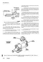
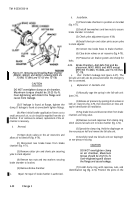
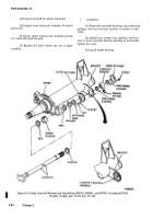
Figure 4-68, Adjusting Plunger Assembly (M967, M969,
and M970 except M970 SN TC-0843, TC-0844,
and TC-103 thru TC-178).
NOTE
The hollow adjusting pawl has teeth on one
end, flats on the side, and a chamfered edge
on the other end. Coat the hollow adjusting
pawl with grease (Item 17, Appendix E) and
Insert it into the guide hole, teeth first, and
with chamfer toward the brake shoe. This
alines the pawl with the actuator teeth and the
flats with the keyway slot. Ensure that pawl is
all the way into the slot In plunger housing.
(3) Install adjusting pawl. Push pawl in flush with
the inside of plunger. Hold the pawl in this position with a
smaIl screwdriver while you install the adjusting sleeve,
Seat the sleeve on bottom of adjusting plunger.
(4) Install spring, gasket, and hollow capscrew.
Tighten capscrew finger tight. Proper meshing of the pawl
and sleeve teeth can now be double checked. Apply grease
(item 17, Appendix E) to threads on adjusting bolt. Turn
the adjusting bolt into the adjusting sleeve until it
bottoms. A clicking sound and ratcheting feel will indicate
meshing of teeth. Now turn the adjusting bolt out three
turns. If there is no clicking sound or ratcheting feel, the
paw] is properly meshed, Tighten hollow capscrew to
15-20 lb.-ft., and unscrew adjusting bolt from adjusting
sleeve. If pawl is not properly meshed, repeat steps (2) and
(3).
(5) Pack a small amount of grease (item 17,
Appendix E) into the underside of single lip plunger seal
and seal lips. Assemble the seal over the adjusting sleeve
in the plunger housing. Push the seal over end of the
adjusting sleeve until the inner lip enters seal groove.
Check by lightly pulling up on seal. Seat the plunger seal
assembly (fig. 4-67) in the plunger housing with seal driver
or a 1¾-inch wrench socket and rawhide mallet.
(6) Apply grease (item 17, Appendix E) to
threads of adjusting bolt (fig. 4-66). Carefully push the
adjusting bolt through the seal and thread it into the
adjusting sleeve. Be careful not to damage the seal. Turn
the adjusting bolt in until head of bolt almost touches the
seal. Do not bottom the bolt on the seal.
g.
Assembly and Adjustment.
(1) Install brake shoe assemblies (para 4-33).
(2) Install wheels hubs, and drum (para 4-49).
(3) Install brake air chambers (para 4-39).
(4) Check and adjust the
clearance (para 4-33).
brake lining-to-drum
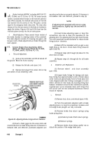
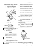
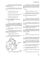
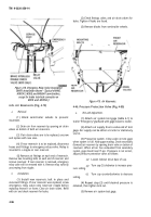
Figure 4-69. Cross-Section of Plunger Housing Showing
Installation of Adjusting Plunger (M967, M969, and M970
except M970 SN TC-0843, TC-0844, and
TC-103 thru TC-178).
4-37.
Brake Air Chamber (Standard) Test and
Replacement, M967, M969, and M970 except
M970 SN TC-0843, TC-0844, and TC-103
thru TC-178 (Fig. 4-70).
a.
Test.
(1) With towing vehicle connected and vehicle
brakes applied, coat the flanges and connect ions on the air
chamber with soapy water.
4-88
Change 3
Back to Top

