TM-9-2330-356-14
SEMITRAILER, TANK: 5000 GALLON, BULK HAUL, SELF LOAD/UNLOAD M967 AND M967A1; SEMITRAILER, TANK: 5000 GALLON, FUEL DISPENSING, AUTOMOTIVE M969 AND M969A1; SEMITRAILER, TANK: 5000 GALLON, FUEL DISPENSING, UNDER/OVERWING AIRCRAFT M970 AND M970A1
TECHNICAL MANUAL; OPERATOR’S, UNIT, DIRECT SUPPORT, AND GENERAL SUPPORT MAINTENANCE MANUAL
OCTOBER 1990
TM-9-2330-356-14 - Page 226 of 528
TM 9-2330-356-14
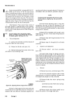
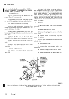
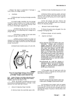
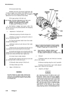
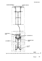
Figure 4-71. Removing and Installing Brake Chamber
(M967A1, M969A1, and M970A1 including M970 SN
TC-0843, TC-0844, and TC-103 thru TC-178).
CAUTION
DO NOT overtighten clamp on air chamber.
Maximum torque should be 20-25 lb.-ft.
Over-tightening will distort the flange and
cause more leakage.
(3) If leakage is found at flange, tighten the
clamp. If leakage is found at connection% tighten fittings.
(4) After initial brake application forces out a
small amount of air, no air should be expelled from the air
chamber. If air continues to exhaust, replacement of the air
chamber is necessary.
b.
Removal.
(1) Open drain valves on the air reservoirs and
allow air to bleed off (fig. 4-79).
(2) Disconnect two brake hoses from brake
chamber (fig. 4-71).
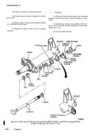
(3) Remove cotter pin and clevis pin securing
yoke to slack adjuster.
(4) Remove two nuts and two washers securing
brake chamber to bracket.
(5) Remove brake chamber.
c .
Repair. No
repair of brake chamber is authorized.
d.
Installation.
(1) Place brake chamber in position on bracket
(fig. 4-71).
(2) Install two washers and two nuts to secure
brake chamber to bracket.
(3) Check yoke adjustment (para 4-34).
(4) Install clevis pin and cotter pinto secure yoke
to slack adjuster.
leaks.
4-39.
a.
(5) Connect two brake hoses to brake chamber.
(6) Close drain valves on air resevoirs (fig. 4-79).
(7) Pressurize air brake system and check for
Brake Chamber—Fail-Safe Test and Re-
placement, M967, M969, and M970 except
M970 SN TC-0843, TC-0844, and TC-103 thru
TC-178.
Test.
Perform leakage test (para 4-37). The
fail-safe unit will also be pressurized when the emergency
line is connected.
b.
Replacement of Fail-Safe Unit.
(1) Manually cage the spring in the fail-safe unit
(para 2-4).
(2) Release air pressure by opening drain valves on
both air reservoirs (fig. 4-79), then disconnect air lines and
tag for identification at installation.
(3) Tag brake hoses and disconnect them from brake
chambers and relay valve.
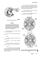
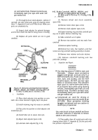
(4) Remove nut and capscrew from clamp ring
which secures fail-safe unit to brake chamber (fig. 4-72).
(5) Spread the clamp ring. Hold the diaphragm on
the non-pressure half and remove the fail-safe unit.
(6) Carefully install new fail-safe unit over diaphragm
on non-pressure housing.
CAUTION
DO NOT overtighten clamp
on air chamber, Maximum
torque should be 20-25 lb.-ft.
Over-thightening will distort
the flange and cause leakage.
(7) Install clamp ring, with capscrew, nuts, and
identification tag (fig. 4-72). Position the ports on the
4-90
Change 3
Back to Top

