TM-9-2350-238-20-1 - Page 745 of 1364
2
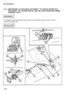
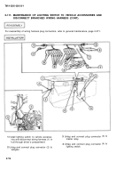
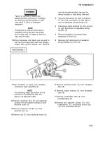
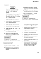
Tag and disconnect
from rear bulkhead.
3
Tag and disconnect
TM 9-2350-238-20-1
plug connector (1)
5
If damaged, remove gasket (6) from
receptacle connector (5).
two shell connectors
6
Tag and disconnect plug connector (7)
(2) from circuit breakers.
from master relay.
4
Remove four screws (3), four washers (4),
7
Remove bulkhead to bulkhead starter
and receptacle connector (5) from front
circuit branched wiring harness (8) from
bulkhead disconnect to starter.
hull through driver's compartment.
For disassembly of wiring harness receptacle connector and plug connectors, refer to general
maintenance, page 2-371.
1
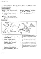
Inspect for broken, damaged, or missing parts.
2
If damaged or missing, replace marker bands. Etch or stamp lead number on new band.
3
For repair of shell connectors, refer to general maintenance, page 2-371.
4
Electrical wires are manufactured items, refer to appendix D.
5
Repair is by replacement of authorized parts (TM 9-2350-238-24P-1).
For reassembly of wiring harness receptacle connector and plug connectors, refer to general
maintenance, page 2-371.
1
2
3
4
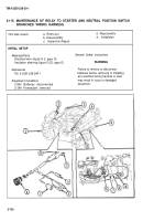
Install bulkhead to bulkhead starter circuit
5
branched wiring harness (8) to hull through
driver’s compartment.
6
Untag and connect plug connector (7) to
master relay.
7
If removed, install new gasket (6) to
receptacle connector (5).
Connect receptacle connector (5) to front
bulkhead disconnect to starter, and install
four washers (4) and four screws (3).
Untag and connect two shell connectors
(2) to circuit breakers.
Untag and connect plug connector (1) to
rear bulkhead.
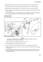
Wiring harnesses and leads are secured to
the hull and components with loop clamps,
straps, clips, ground screws, etc. During
installation, make sure the wiring harness
or lead is secure and all hardware is tight.
2-719
Back to Top

