TM-9-2350-260-20-1-2 - Page 515 of 772
TM 9-2350-260-20-1-2
FUEL-WATER SEPARATOR OPERATIONAL TESTS (2D ENGINE) (Sheet 2 of 11)
NOTE
In order to perform any of the tests in this procedure, they must be performed in
the sequence listed.
MANUAL DRAIN TEST:
1.
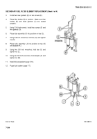
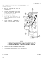
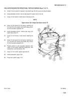
Place drip pan under fuel-water separator (A) and sensor probes (B) and (C).
2.
Using socket, remove three capscrews, lockwashers, and flat washers (D).
Throw lockwashers away.
3.
Using hands, remove clamp (E) from sensor probe wires (B) and (C).
4.
Using socket, loosen capscrew (F) to provide movement of fuel-water separator.
CAUTION
Be very careful not to disturb center
filter element.
Center filter element
must be replaced if disturbed in any
way.
NOTE
It may be necessary to use hammer
and punch to unseat sensors (B) and
(C) by tapping upward on edge of
sensor retaining nut.
5.
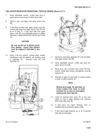
Using 1/2 inch wrench to hold sensor retaining nut (G), use 9/16 inch wrench and remove upper sensor (B) from
fuel-water separator.
6.
Using 7/16 inch wrench, open and then close bleed cap (H).
7.
Check to see if fluid level is above upper sensor probe (B) hole by noting leakage from upper sensor probe (B) hole
when bleed cap (H) is open.
8.
Using 1/2 inch wrench, remove sensor retaining nut (G).
9.
Using 1/2 inch wrench to hold sensor retaining nut (J), use 9/16 inch wrench and remove lower sensor (C) from
fuel-water separator.
10.
Using adjustable wrench, install pipe plug into lower sensor probe (C) hole.
NOTE
It may be necessary to remove capscrew (F) and move fuel-water separator (A)
before lower sensor (C) can be removed.
If removed, capscrew-(F) should be
reinstalled after step 10.
Go on to Sheet 3
TA148321
7-246
Back to Top


