TM-9-2350-260-20-1-3 - Page 38 of 783
TM 9-2350-260-20-1-3
GENERATOR VOLTAGE ADJUSTMENT (Sheet 2 of 2)
NOTE
There is a positive (+) and a negative
(-) shown on slave receptacle.
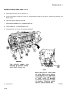
5.
Set multimeter to 0-50 volt DC range.
6.
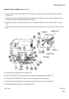
With one person in drivers compartment with
multimeter, place red test lead (D) in positive (+) (E)
side and black test lead in negative (-) side of slave
receptacle (F).
7.
Person in driver's compartment, start engine
(TM 9-2350-260-10) and run for one half hour at
1000 RPM.
8.
Turn on service headlights (TM 9-2350-260-10).
NOTE
Make sure person in turret has full
view of multimeter.
9.
Person in turret, using screwdriver, adjust voltage
control box (B) until multimeter indicates 26-30 VDC.
10. If
voltage
cannot
be
obtained,
refer
to
troubleshooting (page 4-406).
11. Shut down engine and turn off service headlight
(TM 9-2350-260-10).
12. Install access plug (C) in voltage control box (B).
13. Remove test leads from slave receptacle (F).
End of Task
TA147058
10-26
Back to Top

