TM-9-2350-260-20-1-3 - Page 686 of 783
TM 9-2350-260-20-1-3
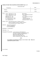
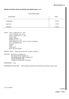
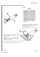
GREASE ACTUATED TRACK ADJUSTING LINK REPLACEMENT (Sheet 1 of 7)
PROCEDURE INDEX
PROCEDURE
PAGE
Removal
14-64.1
Installation
14-64.4
TOOLS:
15/16 in.
socket with 1/2 in.
drive
Slip joint pliers
15/16 in.
socket with 3/4 in.
drive
3/8 in.
combination box and open
1-1/8 in.
socket with 1/2 in.
drive
end wrench
Ratchet with 1/2 in.
drive
3/4 in.
combination box and open
Ratchet with 3/4 in.
drive
end wrench
5 in.
extension with 1/2 in.
drive
Torque wrench with 3/4 in. drive
5 in.
extension with 3/4 in.
drive
(0-600 ft-lb)(0-813 N
•
m)
12 in.
adjustable wrench
Lifting device (2,000 lbs.
capacity)
SPECIAL TOOLS:
Slide hammer puller (Item 12, Chapter 3, Section I)
Remover and replacer tool (Item 18, Chapter 3, Section I)
Wire rope assembly (Item 23, Chapter 3, Section I)
SUPPLIES:
Grease (Item 36, Appendix D)
Lockwasher (MS35338-67)
Pin, cotter (MS24665-497)
REFERENCE:
TM 9-2350-260-10
PERSONNEL:
Two
PRELIMINARY PROCEDURES:
Loosen track tension (TM 9-2350-260-10)
Disconnect track between compensating idler wheel
and number 1 roadwheel (TM 9-2350-260-10)
Remove front fender (page 16-64)
Remove shock absorber (page 14-95)
Remove compensating idler wheel (page 14-50)
NOTE
This adjusting link replacement procedure is for left side of tank.
Right side
adjusting link procedure is similar.
Go on to Sheet 2
TA248468
14-64
Change 1
Back to Top


