TM-9-2350-261-20-2 - Page 631 of 1008
INITIAL SETUP:
Maintenance Level
Unit
Materials/Parts
C leaning com po und (
WP 0782 00
, Item
16
)
Screw (16)
Personnel Required
Unit Mechanic
References
See your -10
Equipment Condition
Engine stopped/shutdown (see your -10)
Carrier blocked (see your -10)
Trim vane lowered (see your -10)
Power plant front access door open (see your -10)
REMOVAL
NOTE
Place gear range selector in neutral position. Set or release differential steering brakes as
required to rotate or lock shaft during removal or installation (see your -10).
1.
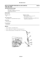
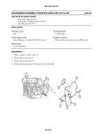
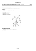
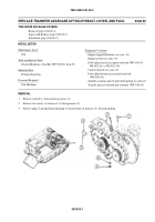
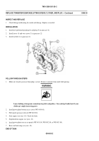
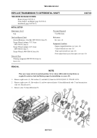
Remove eight screws (1), flat washers (2), and shaft (3) from two universal joints (4). Discard screws.
2.
Remove eight screws (5), flat washers (6), and two universal joints (4) from differential yoke (7) and transmission
yoke (8). Discard screws.
3.
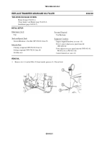
Remove yoke (7) from differential (9).
General Mechanic’s Tool Kit (WP 0780 00, Item 29)
Torque Wrench Adapter, 7C U-Joint
(WP 0780 00, Item 6)
Torque Wrench Adapter, 6C U-Joint
(WP 0780 00, Item 7)
Torque Wrench (WP 0780 00, Item 103)
T
s
o
l
o
o
l
o
s
T
a
l
n
a
d
i
S
c
pe
THIS WORK PACKAGE COVERS:
Removal (page 0347 00-1).
Clean, Inspect, and Repair (page 0347 00-2).
Installation (page 0347 00-2).
REPLACE TRANS MISS IO N TO DIFFERENTIAL S HAFT
0347 00
TM 9-2350-261-20-2
034700-1
Back to Top

