TM-9-2350-261-20-2 - Page 835 of 1008
REPLACE TRANSMISSION AND LOWER ACCELERATOR LINKAGE — Continued
3.
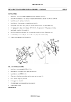
Install range selector lever (13) on transmission shaft (14) with off-set of lever toward transmission and clamp-screw
hole aligned with flat on shaft. Secure with screw (15) and new locknut (16).
4.
Install throttle valve lever (17) on transmission shaft (18) with off-set side of lever away from transmission and
clamp-screw hole aligned with flat on shaft. Secure with screw (19) and new locknut (20).
5.
Install range selector link (6) on transmission arm (13). Secure with screw (21) and new locknut (22).
6.
Install throttle valve link (5) on transmission arm (17). Secure with screw (23) and new locknut (24).
7.
Install transmission range selector to cross-shaft link (25) on transmission arm (3). Secure with screw (26) and new
locknut (27).
8.
Install accelerator link (28) on accelerator cross-shaft arm (2). Secure with screw (29) and new locknut (30).
039700-5
0397 00
TM 9-2350-261-20-2
Back to Top

