TM-9-2350-261-20-3 - Page 530 of 932
TM 9-2350-261-20-3
ADJUST RAMP LOCK (M1064 ONLY) — Continued
0559 00
6.
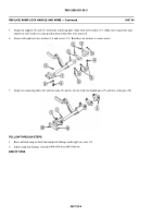
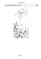
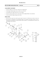
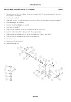
Install eight new key washers (1). Tighten eight screws (2) and bend washer keys to secure screws. If shimmed right,
catch (3) on lever (4) will engage firmly with striker (5).
7.
For carriers with flat shaped rod (6), place link (7) in clevis (8). Secure with headed pin (9) and new cotter pin (10).
8.
Start engine (see your -10).
9.
Raise and lock ramp (see your -10).
10. Stop engine (see your -10).
NOTE
The steps below are for one side of ramp lock adjustment. Adjust both sides of carrier at
the same time.
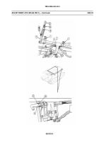
11. Loosen locknut (11) on forward clevis (8).
NOTE
Making linkage shorter pulls the ramp in and puts a tight squeeze on the ramp seal. Making
linkage longer lessens the squeeze on the seal.
12. Turn rod (6), as needed, to make sure ramp seal is compressed right. Tighten locknut (11) on clevis (8).
13. Lower ramp (see your -10). Return lever (4) to closed position.
14. Remove two screws (12) and lockwashers (13) from trip plate (14). Discard lockwashers.
0559 00-4
Back to Top

