TM-9-2350-277-20-5 - Page 924 of 1047
TM 9-2350-277-20-5
REPAIR/REPLACE MORTAR FIRE CONTROL SYSTEM CABLES (MFCS)
(M1064A3 ONLY) — Continued
0812 14
NOTE
Steps 36 - 52 apply to cable 3W1, power/data cable for commander’s interface (CI).
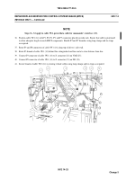
36. Position cable 3W1 (14) with P1, P2, P4, P5, and P7 connectors placed on radio rack. Ensure that cable is positioned
to allow adequate length to reach MFCS components. Bundle P2 and P7 branches using loop clamps and tie straps
as required.
37. Route P3 and P8 connectors of cable 3W1 (14) along top of driver’s side wall.
38. Route P3 branch of cable 3W1 (14) behind fire extinguisher hard line and at a clear distance from line.
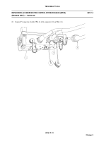
39. Connect P3 connector of cable 3W1 (14) to J1 connector (26) on VMS (25).
40. Connect P8 connector of cable 3W1 (14) to J1 connector (23) on DD (24).
41. Secure branch of cable 3W1 (14) to existing vehicle cables using loop clamps and tie straps as required.
0812 14-23
Change 5
Back to Top


