TM-9-2350-277-20-5 - Page 917 of 1047
TM 9-2350-277-20-5
REPAIR/REPLACE MORTAR FIRE CONTROL SYSTEM CABLES (MFCS)
(M1064A3 ONLY) — Continued
0812 14
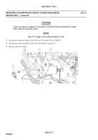
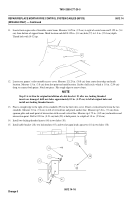
11. Locate front engine side of turntable center beam. Measure 3.625 in. (9.2 cm) to right of center beam and 2.125 in. (5.4
cm) from bottom of support beam. Mark location and drill 0.159 in. (0.4 cm) hole (57) to 1.0 in. (2.54 cm) depth.
Thread hole with 10-32 tap.
12. Locate rear gunner’s side turntable access cover. Measure 12.125 in. (30.8 cm) from center front edge and mark
location. Measure 1.5 in. (3.8 cm) from first point and mark location. Scribe a half circle, which is 1.0 in. (2.54 cm)
deep, to connect both points. Notch out piece. File rough edges to remove burrs.
NOTE
Step 13 is written for original installation of cable bracket. If, after use, locking threaded
inserts are damaged, drill new holes approximately 0.5 in. (1.27 cm) to left of original holes and
install new locking threaded inserts.
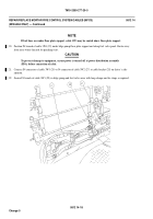
13. Place a straight edge to the right of two standoffs (59) for the fuel valve cover. Pencil a vertical line between the two
standoffs. Measure 3.0 in. (7.6 cm) to left of vertical line and pencil another line. Measure up 3.0 in. (7.6 cm) from
sponsonplateandmarkpointofintersectionwithsecondvertical line. Measure up 1.75 in. (4.45 cm) and mark second
intersection point. Drill a 0.201 in. (0.51 cm) hole (58) at both points, to a depth of 1.0 in. (2.54 cm).
14. Install two locking threaded inserts (60) in two holes (58).
15. Install cable bracket (28), two lockwashers (45), and two hexagon head capscrews (18) in two holes (58).
0812 14-16
Change 5
Back to Top


