TM-9-2520-238-34 - Page 220 of 319
TM 9-2520-238-34
REPAIR OUTPUT SHAFT ASSEMBLIES — Continued
0024 00
3.
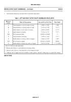
Check the parts dimensions with chart below to determine replacement.
Table 1. LEFT AND RIGHT OUTPUT SHAFT ASSEMBLIES WEAR LIMITS
Reference
Letter
Point of Measurement
Size and Fit of New Parts
Wear Limits
A
Outside diameter at oil seal surface of shaft
1.9980 to 2.0020
1.9960
B
Outside diameter at bearing surface of shaft
1.7716 to 1.7720
(*)(**)
C
Inside diameter at seal surface of retainer
2.6850 to 2.6870
(*)(***)
D
Inside diameter of bearing
1.7712 to 1.7717
(*)(**)
D-B
Fit of bearing on shaft
0.0001L to 0.0008T
(*)
E
Outside diameter of bearing
3.3459 to 3.3465
(*)(**)
F
Inside diameter at bearing surface of support
3.3464 to 3.3472
3.3477
F-E
Fit of bearing in support
0.0013L to 0.0001T
0.0018L
G
Inside diameter at piston ring surface of support
2.9370 to 2.9390
(****) 2.9450
* Must be within new parts dimensions.
** Measure only if there is visual indication of bearing turning.
*** Measure only if there is visual indication of seal turning in retainer.
**** Measure only if support has been reworked to remove grooves caused by sealing ring or to repair other damage.
END OF TASK
0024 00-14
Back to Top


