TM-9-2520-270-34 - Page 678 of 933
TM 9-2520-270-34
REPAIR LEFT-HAND OUTPUT CARRIER ASSEMBLY
DESCRIPTION
This task covers: Disassemble (page 4-345), Assemble (page 4-347).
INITIAL SETUP
Tools:
Personnel Required:
General mechanic’s tool kit:
Track Veh Rep 63H10
automotive — (Item 33, App C)
Torque wrench – (Item 100, App C)
References:
Wire-twister pliers — (Item 107, App C)
TM 9-214
Materials/Parts:
Equipment Conditions:
Lockwire – (Item 5, App B)
Sealant compound – (Item 11, App C)
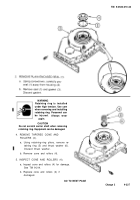
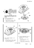
1. REMOVE 12 SCREWS (1) FROM
SERVICE BRAKE HUB (2).
a. Remove and discard Iockwire (3)
securing 12 screws (1).
b. Remove 12 screws (1) from hub (2).
Left-hand output carrier assembly on
workbench, See page 4-336.
2. REMOVE HUB (2) FROM OUTPUT
CARRIER (4).
3. INSPECT HUB (2) FOR DAMAGE.
See page 2-5.
a. Replace hub (2) if damaged.
GO TO NEXT PAGE
Change 1
4-345
Back to Top

