TM-9-2520-272-40 - Page 177 of 620
TM 9-2520-272-40
0023
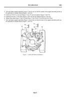
15.Put the right cover assembly (Figure 11, Item 9) on two wooden blocks (Figure 11, Item 14) so that the inside
of the right cover assembly points up.
CAUTION
When you push the brake apply shaft through the seal, be sure that the spring in the seal stays
in place. Put one hand on outside of right cover, over the brake apply shaft bore, and run a
f nger around the spring in the seal to keep the spring in place while the end of the shaft comes
through. If the spring does not remain in its proper position, the seal will leak.
NOTE
If they have been previously removed, brake apply cam and brake adjusting links should be
installed in right cover assembly before f nal installation steps of right brake support assembly
are performed.
When installing right brake support assembly on right cover assembly, the following alignments
should be checked:
• Splined (taped) end of right brake apply cam shaft goes through thrust washer on right cover
assembly and into needle bearing.
• Two long brake reaction pins go into pin holes in right brake support assembly.
• Four short brake reaction pins go into pin holes in right brake support assembly.
16.Turn right brake support assembly (Figure 11, Item 8) over so that the outside points up. Put right brake support
assembly on right cover assembly (Figure 11, Item 9).
17.Check that the two long brake reaction pins (Figure 11, Item 24) and four short reaction pins (Figure 11, Item
23) are aligned with the pin holes in the right brake support assembly (Figure 11, Item 8).
Back to Top


