TM-9-2520-272-40 - Page 182 of 620
TM 9-2520-272-40
0024
REPAIR RIGHT BRAKE SUPPORT ASSEMBLY
NOTE
Make sure that the right brake support assembly is on two wooden blocks before you begin
repair procedures.
Inspect the right brake support assembly for serviceability. Replace all defective pins, tubes,
plugs, bearings, and races. Do not remove or replace serviceable components.
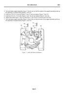
1. Make sure that the right brake support assembly is on two wooden blocks (Figure 1, Item 1) so the external
side points up.
NOTE
Remove the tube coupling only if necessary.
2. Tap the center hole of tube coupling (Figure 1, Item 3) with a 3/8-16 tap to a depth of about six to eight threads.
3. Put a slide hammer into the tube coupling (Figure 1, Item 3), and tap upward to remove the tube coupling
(Figure 1, Item 3).
4. Clean out all metal shavings fully from right brake support assembly.
5. Push the long brake reaction pin (Figure 1, Item 2) from the right brake support assembly (Figure 1, Item 6).
6. Push two dowel pins (Figure 1, Item 5) from the right brake support assembly (Figure 1, Item 6).
NOTE
Remove the tube coupling only if necessary.
7. Tap the center hole of tube coupling with a 1/2-13 tap to a depth of about six to eight threads
8. Put a slide hammer into the tube coupling (Figure 1, Item 4), and tap upward to remove the tube coupling
(Figure 1, Item 4).
9. Clean out all metal shavings fully from right brake support assembly.
0024
‐
2
Back to Top


