TM-9-2520-272-40 - Page 178 of 620
TM 9-2520-272-40
0023
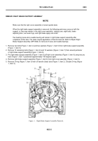
18.Place one hand on the outside of the right cover assembly (Figure 13, Item 9) over the right brake apply cam
shaft (Figure 13, Item 27) bore and run f nger around and over the spring (Figure 12, Item 25) in the seal (Figure
12, Item 26) until taped end of right brake apply cam shaft (Figure 13, Item 27) comes through seal.
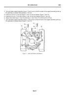
19.Push down on right brake support assembly (Figure 13, Item 8) and lightly move right brake support assembly
back and forth until it slides down over pins (Figure 13, Item 23) and (Figure 13, Item 24). Right brake support
assembly (Figure 13, Item 8) is properly installed when there is about 0.125 in. (3.175 mm) gap between right
brake support assembly (Figure 13, Item 8) and right cover assembly (Figure 13, Item 9).
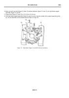
20.Install two 7/16-14 x 1-3/4 inch bolts (Figure 13, Item 4) and washers (Figure 13, Item 5) in right brake support
assembly (Figure 13, Item 8).
21.Install 12 7/16-14 x 1-1/2 inch bolts (Figure 13, Item 6) and washers (Figure 13, Item 7) around perimeter of
right brake support assembly (Figure 13, Item 8).
22.Torque bolts (Figure 13, Item 4) and (Figure 13, Item 6) evenly to 54 to 65 lb-ft (73 to 88 N·m).
Back to Top


