TM-9-2815-200-35
ENGINE, WITH CONTAINER:TURBOSUPERCHARGED, DIESEL ,FUEL INJECTION ,90-DEGREE “V” TYPE, AIR - COOLED ,12 - CYLINDER , ASSEMBLY ;MODELS AVDS-1790-2M (2815-856-4996), AVDS-1790-2A AND AVDS-1790-2AM (2815-856-9005)
TECHNICAL MANUAL; DIRECT SUPPORT, GENERAL SUPPORT AND DEPOT MAINTENANCE MANUAL INCLUDING REPAIR PARTS AND SPECIAL TOOLS LISTS
TM-9-2815-200-35 - Page 87 of 779
Remove
1. Remove starter assembly (A) from starter adapter.
2. Remove and discard mounting gasket (B).
Install
1. Position new mounting gasket (B) on starter adapter.
2. Position starter assembly (A) on starter adapter.
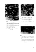
3. Position suitable blocks (A, fig. 4-7) under starter
assembly for support.
Figure 4-8. Removing or installing
starter assembly.
Note.
It is of
utmost importance
that th e
starter support, cradle, and "U" bolt be installed
in
a manner that will not disturb starter
mounting alinement and still furnish adequate
support to minimize vibration. Misalignment of
0.010-in. in any direction is sufficient to cause a
leak (pressure loss) between the starter mounting
flange and the starter housing. Refer t o
paragraph 8-2 for procedure to determine if
there is a pressure loss.
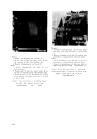
1. Position the assembled support and cradle on oil pan
and install four hexagon head bolts (A) and plain
washers. Tighten only until bolt heads engage the
washers (finger-tight).
2. Loosen four self-locking nuts (B) securing cradle to
support allowing cradle studs to move freely in
elongated holes in support.
3. Position the “U” bolt over the starter and secure to
cradle with two clamping bars and self-locking nuts
(C). Torque tighten nuts evenly.
4. Torque tighten the four self-locking nuts (B) securing
cradle to support, then torque tighten the four hexagon
head bolts (A) securing support to oil pan. Secure oil
pan bolts with locking wire (A, fig. 4-6).
Figure 4-9. Installing starter support, cradle,
and "U" bolt.
4-5
Back to Top


