TM-9-2815-200-35
ENGINE, WITH CONTAINER:TURBOSUPERCHARGED, DIESEL ,FUEL INJECTION ,90-DEGREE “V” TYPE, AIR - COOLED ,12 - CYLINDER , ASSEMBLY ;MODELS AVDS-1790-2M (2815-856-4996), AVDS-1790-2A AND AVDS-1790-2AM (2815-856-9005)
TECHNICAL MANUAL; DIRECT SUPPORT, GENERAL SUPPORT AND DEPOT MAINTENANCE MANUAL INCLUDING REPAIR PARTS AND SPECIAL TOOLS LISTS
TM-9-2815-200-35 - Page 92 of 779
Note .
Similar procedures are required t o
remove the left and right turbosupercharges .
For instructional purposes, removal of the lef t
turbo supercharger is described. Remova l
procedures for the right turbosupercharger ar e
the same, except for the relocated oil filler tube
installation and the generator air exhaust tub e
and cap .
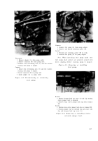
Figure 4-18. Loosening or tightening oil fille r
upper and lower tube hose connectio n
(relocated oil filler tube installation) .
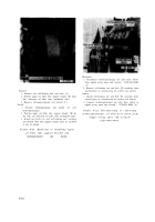
Remove
1. Remove one bolt (A) attaching upper oil filler tube
support bracket to turbosupercharger tie rod.
2. Remove one bolt (B) and lock washer attaching upper
oil filler tube support clamp to tie rod.
3. Remove one bolt (C) and self-locking nut attaching
upper oil filler tube support clamp to support bracket.
4. Remove upper oil filler tube (D) from lower left rear
shroud plate.
Install
1. Position upper oil filler tube (D) through aperture in
lower left rear shroud plate. Make cure lower end of
tube enters hose connection (fig. 4-18).
2. Install one bolt (C) and self-locking nut securing
upper oil filler tube support clamp to support bracket.
3. Install one bolt (B) and lock washer securing upper oil
filler tube support clamp to turbosupercharger tie rod.
4. Install one bolt (A) securing upper oil filler tube
support bracket to tie rod.
Figure 4-19. Removing or installing uppe r
oil filler tube (relocated oil filler tube
installation) .
4-1 0
Back to Top


