TM-9-2815-200-35
ENGINE, WITH CONTAINER:TURBOSUPERCHARGED, DIESEL ,FUEL INJECTION ,90-DEGREE “V” TYPE, AIR - COOLED ,12 - CYLINDER , ASSEMBLY ;MODELS AVDS-1790-2M (2815-856-4996), AVDS-1790-2A AND AVDS-1790-2AM (2815-856-9005)
TECHNICAL MANUAL; DIRECT SUPPORT, GENERAL SUPPORT AND DEPOT MAINTENANCE MANUAL INCLUDING REPAIR PARTS AND SPECIAL TOOLS LISTS
TM-9-2815-200-35 - Page 89 of 779
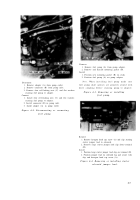
1. Remove one self-locking nut (A).
2. Remove clamping bar (B).
3. Loosen two self-locking nuts (C).
4. Cut locking wire and remove four bolts (D) and flat
washers.
5. Remove generator support and cradle (E) and “U”
bolt as an assembly.
Figure 4-12. Removing generator support ,
cradle, and “U” bolt .
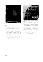
Disconnect
1. Remove two bolts (A) and lock washers.
2. Remove and discard oil drain tube gasket (B).
3. Loosen generator boot to exhaust tube hose clamp
(C).
4. Remove two generator boot hose clamps (D).
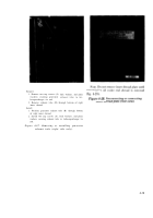
5. Rotate generator boot (E) to position shown in figure
4-14, then remove hose clamp (C).
Connect
1. Position generator boot (E) to install exhaust tube
hose clamp (C) on boot and rotate boot to position
shown.
2. Install two generator boot hose clamps (D).
3. Tighten hose clamp (C).
4. Position new oil drain tube gasket (B) on oil drain
tube.
5. Install two bolts (A) and lock washers securing oil
drain tube to oil pan.
Figure 4-13. Disconnecting or connectin g
cylinder head right rear oil drain tube and
generator boot hose clamps .
4-7
Back to Top


