TM-9-2815-200-35
ENGINE, WITH CONTAINER:TURBOSUPERCHARGED, DIESEL ,FUEL INJECTION ,90-DEGREE “V” TYPE, AIR - COOLED ,12 - CYLINDER , ASSEMBLY ;MODELS AVDS-1790-2M (2815-856-4996), AVDS-1790-2A AND AVDS-1790-2AM (2815-856-9005)
TECHNICAL MANUAL; DIRECT SUPPORT, GENERAL SUPPORT AND DEPOT MAINTENANCE MANUAL INCLUDING REPAIR PARTS AND SPECIAL TOOLS LISTS
TM-9-2815-200-35 - Page 91 of 779
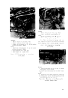
Remove
1. Remove six self-locking nuts (A).
2. Remove and discard generator mounting gasket (B).
Install
1. Position new generator mounting gasket (B) on studs.
2.
Install, but do not tighten, six self-locking nuts (A).
Figure 4-16. Removing or installin g
generator gasket .
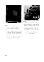
Note .
It is important that the generato r
cradle, support, an d “U” bolt be installed in a
manner that will not disturb generator alinemen t
and still furnish adequate support to minimiz e
vibration .
1. Position the assembled generator cradle, support, and
“U” bolt and install four bolts (A) and flat washers.
Tighten bolts only until bolt heads engage washers
(finger-tight).
2. Install “U” bolt over generator and secure with one
clamping bar and self-locking nut (B) and torque
tighten. Torque tighten two self-locking nuts (C).
3. Torque tighten four bolts (A) and secure with locking
wire as shown in figure 4-12.
Figure 4-17. Installing generator support ,
cradle, and “U” bolt .
4-9
Back to Top


