TM-9-2815-205-24 - Page 536 of 856
DISASSEMBLY - Continued
12.
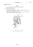
Remove six fuel nipples (Figure 5, Item 9) and six copper flat washers (Figure 5, Item 35) from cylinder
head. Discard copper flat washers.
13.
If necessary, remove three expansion plugs (Figure 5, Item 37) from cylinder head, one from inboard side
and two from outboard side. Discard plugs.
14.
If necessary, remove sleeve (Figure 5, Item 40) from inboard side of cylinder head.
CAUTION
Inspect fuse plug. If fuse plug is melted, cylinder head assembly was overheated.
Thoroughly inspect cylinder head assembly for cracks and other heat related damage.
NOTE
Pressure check cylinder head at this point as described in Test and Inspection.
15.
Remove two screws (Figure 5, Item 41), two lockwashers (Figure 5, Item 42), cover (Figure 5, Item 43), and
gasket (Figure 5, Item 44) from rear of cylinder head. Discard lockwashers and gasket.
16.
If necessary, remove four studs (Figure 5, Item 48) from outboard side of cylinder head.
17.
Remove fuse plug (Figure 5, Item 47) and adapter (Figure 5, Item 46) from outboard side of cylinder head.
18.
Remove three expansion plugs (Figure 5, Item 45) from outboard side of cylinder head. Discard plugs.
19.
Remove four pipe plugs (Figure 5, Item 38) from inboard side of cylinder head.
20.
Remove pipe plug (Figure 5, Item 36) from each end of cylinder head.
NOTE
Model 5063-5392 uses one threaded plug (Figure 5, Item 39) at rear of left
cylinder head.
Models 5063-5393 and 5063-539L use one threaded plug (Figure 5, Item 39) at
both ends of left cylinder head.
21.
If necessary, remove six threaded plugs (Figure 5, Item 39), except where noted, from each end of head.
Two plugs are located at each end and four plugs are located on inboard side of cylinder head.
TM 9-2815-205-24
0083
0083-6
Back to Top


