TM-9-2815-205-24 - Page 533 of 856
DISASSEMBLY - Continued
4.
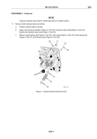
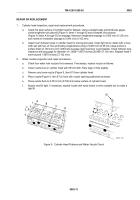
For all except model 5063-5299: if necessary, remove check valve (Figure 2, Item 10), oil supply plug
(Figure 2, Item 11), and strainer (Figure 2, Item 12) from throttle delay housing (Figure 2, Item 6).
5.
Swing left rocker arm (Figure 2, Item 16), injector rocker arm (Figure 2, Item 17), and right rocker arm
(Figure 2, Item 18) away from each injector. Remove injector clamp screw (Figure 2, Item 13), convex
washer (Figure 2, Item 14), and clamp (Figure 2, Item 15) from each injector.
6.
Remove three fuel injectors (Figure 2, Item 7) from cylinder head.
7.
Loosen nine push rod nuts (Figure 2, Item 19) at upper end of push rods (Figure 2, Item 20) next to rocker
arm clevis. Remove nine rocker arms (Figure 2, Items 16, 17, and 18) from push rods by unscrewing
rocker arms.
7
6
10
12
13
16
17
18
19
20
11
14
15
MAINT_247
Figure 2.
Cylinder Head Rocker Arm and Injector Removal.
TM 9-2815-205-24
0083
0083-3
Back to Top


