TM-9-2815-205-24 - Page 537 of 856
DISASSEMBLY - Continued
9
47
48
37
37
35
39
39
39
36
41
42
43
44
45
46
36
37
38
39
40
OUTBOARD RIGHT
REAR VIEW
INBOARD LEFT
REAR VIEW
MAINT_250
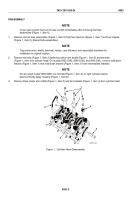
Figure 5.
Cylinder Head Freeze Plug Removal.
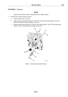
22.
On models 5063-5393, and 5063-539L, remove tee (Figure 6, Item 50) from elbow (Figure 6, Item 51) at
front of right cylinder head.
23.
Remove elbow (Figure 6, Item 51), coupling (Figure 6, Item 52), and elbow (Figure 6, Item 53) from front of
right cylinder head.
24.
Remove pipe plug (Figure 6, Item 49) and elbow (Figure 6, Item 54) from front of left cylinder head.
49
54
*50
51
LEFT FRONT VIEW
RIGHT FRONT VIEW
52
53
* MODELS 5063-5393 AND 5063-539L ONLY
MAINT_251
Figure 6.
Cylinder Head Fuel Line Fitting Removal.
TM 9-2815-205-24
0083
0083-7
Back to Top


