TM-9-2815-205-24 - Page 540 of 856
TEST AND INSPECTION
Pressure check cylinder head procedures are as follows:
a.
Ensure inside exhaust manifold studs (Figure 8, Item 48), adapter (Figure 8, Item 46), fuse plug
(Figure 8, Item 47), three expansion plugs (Figure 8, Item 45), gasket (Figure 8, Item 44), cover
(Figure 8, Item 43), and two bolts (Figure 8, Item 41) are in place to pressure check cylinder head.
b.
Install fabricated tapped end blocking plate (Figure 8, Item 64), gasket (Figure 8, Item 63), and two
bolts (Figure 8, Item 41) over hole at end of cylinder head (WP 0080). Tighten bolts securely.
c.
Install four fabricated top blocking plates (Figure 8, Item 61), four gaskets (Figure 8, Item 62), eight
bolts (Figure 8, Item 60), sixteen flat washers (Figure 8, Item 66), and eight nuts (Figure 8, Item 65)
over eight water holes on fire deck (WP 0080). Tighten nuts securely.
d.
Install scrap or dummy injectors to properly seal injector tubes. Torque injector clamp screws to
20–25 lb-ft (27–34 N·m).
e.
Connect an air supply line with regulator to fabricated end plate (Figure 8, Item 64). Pressurize
cylinder head water jacket to 40 PSI (276 kPa).
f.
Immerse cylinder head in a tank of water heated to 180–200°F (82–93°C) for twenty minutes to heat
head. Observe water in tank for bubbles which indicate a leak or crack. Check for leaks at top and
bottom of injector tubes, oil gallery, exhaust ports, fuel galleries, and at top and bottom of
cylinder head.
g.
Relieve air pressure and remove cylinder head from water tank. Remove air supply line, regulator, end
plate, scrap injectors, and blocking plates from cylinder head.
47
43
41
48
46
61
60
65
45
66
62
63
64
41
44
MAINT_253
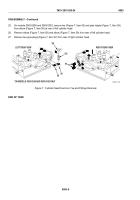
Figure 8.
Cylinder Head Test and Inspection.
END OF TASK
TM 9-2815-205-24
0083
0083-10
Back to Top


