TM-9-2815-205-24 - Page 541 of 856
REPAIR OR REPLACEMENT
1.
Cylinder head inspection, repair and replacement procedures:
a.
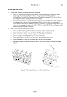
Check fire deck surface of cylinder head for flatness. Using a straight edge and thickness gages,
check lengthwise (six places) (Figure 9, Items 1 through 6) and crosswise (four places)
(Figure 9, Items A through D) for warpage. Maximum lengthwise warpage is 0.005 inch (0.125 mm)
and maximum crosswise warpage is 0.004 inch (0.102 mm).
b.
Inspect cam follower bores in cylinder head for scoring and wear. Clean light score marks with crocus
cloth wet with fuel oil. Non-protruding longitudinal scoring of 0.003 inch (0.08 mm) deep and bore
surface finish of 120 micro inch Arithmetic Average (AA) maximum is permissible. Check follower bore
clearance with plug gage for diameter of 1.0626–1.0670 inches (26.990–27.102 mm). Replace head if
worn beyond 1.0670 inches (27.102 mm).
2.
Water nozzles inspection and repair procedures:
a.
Check four water hole nozzles for looseness. If necessary, replace nozzle as follows:
b.
Clean nozzle bore in cylinder head with 5/8 inch drill. Flare edge of hole slightly.
c.
Remove any loose nozzle (Figure 9, Item 67) from cylinder head.
d.
Place nozzle (Figure 9, Item 67) in bore with nozzle opening positioned as shown.
e.
Press nozzle flush to 0.0312 inch (0.792 mm) below surface of cylinder head.
f.
Nozzle must fit tight. If necessary, expand nozzle with wood dowel or other suitable tool to make a
tight fit.
67
A
B
C
D
1
2
4
3
5
6
MAINT_254
Figure 9.
Cylinder Head Flatness and Water Nozzle Check.
TM 9-2815-205-24
0083
0083-11
Back to Top

