TM-9-2815-205-24 - Page 534 of 856
DISASSEMBLY - Continued
8.
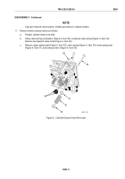
Rest cylinder head on its side and remove six screws (Figure 3, Item 21), six lockwashers
(Figure 3, Item 22), and three cam follower guides (Figure 3, Item 28). Discard lockwashers.
9.
Remove nine cam follower spring retainers (Figure 3, Item 27) from bores in cylinder head.
10.
Pull nine cam followers (Figure 3, Item 23) and nine push rod (Figure 3, Item 20) assemblies from bottom of
cylinder head. Remove spring (Figure 3, Item 25), push rod nut (Figure 3, Item 19), upper spring seat
(Figure 3, Item 26), and lower spring seat (Figure 3, Item 24) from nine push rods.
21
22
27
23
28
20
20
19
26
24
25
23
20
MAINT_248
Figure 3.
Cylinder Head Cam Follower Guides Removal.
TM 9-2815-205-24
0083
0083-4
Back to Top


