TM-9-2815-205-34 - Page 129 of 596
TM 9-2815-205-34
3-2. TURBOCHARGER REMOVAL/INSTALLATION (MODEL 5083-5392)
This task covers: a. Removal
b. installation
INITIAL SETUP
MODELS
MATERIALS/PARTS
5063-5392
Lockwashers (App F, Item 100)
Nuts, self-locking (App F, Item 108)
TOOLS AND SPECIAL TOOLS
Gasket (App F, Item 81)
Tool kit, general mechanics (App B, Item 107 )
Gasket (App F, Item 35)
Wrench, torque (App B, Item 116
Pliers, wire twister (App B, Item 76)
EXPENDABLE/DURABLE SUPPLIES
Wrench, torque (App B, Item 118)
Wire (App C, Item 57)
Tape, masking (App C, Item 52)
a. Removal
(1)
(2)
(3)
(4)
(5)
(6)
(7)
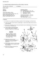
Cut wires (1) on insulator set (2). Remove insulator set from turbocharger (3). Discard wires.
Loosen two clamps (4) and hose (5) at turbocharger air outlet. Slide clamps and hose onto air
inlet housing (6).
Remove four self-locking nuts (7), four special washers (8), and turbocharger (3) from exhaust
tee (9). Discard self-locking nuts.
Loosen compressor housing coupling
(10) and rotate outlet of compressor
housing (11) away from air inlet housing,
CAUTION
Tape all openings of turbo-
charger after removal from en-
gine to keep foreign particles
from entering and damaging
turbocharger blades.
Remove two screws (12), two
lockwashers (13), and turbocharger (3)
from air inlet housing (6). Discard
lockwashers.
Remove gasket (14) from air inlet housing
(6) and gasket (15) from exhaust tee (9).
Discard gaskets.
Remove two clamps (4 and hose (5)
from air inlet housing (6).
3-4
Back to Top


