TM-9-2815-205-34 - Page 251 of 596
TM 9-2815-205-34
3-40. FLYWHEEL ASSEMBLY REPLACEMENT (Cmt)
(7) Turn bolts an additional 90-120 degrees
to obtain required clamping force.
NOT E
On model 5063-5299, meas-
ure flywheel face runout before
installing clutch plate assem-
bly.
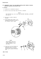
(8) 0n model 5063-5299, install clutch plate
assembly (2) and eight bolts (1) to
flywheel assembly (3). Torque bolts to
30-35 Ib-ft (41-47 NŽm).
e. Testing
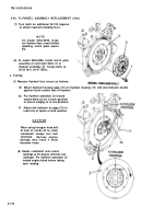
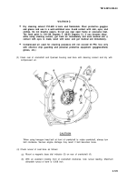
(1) Measure flywheel face runout as follows:
(a)
(b)
(c)
Mount flywheel housing gage (10) on flywheel housing (11) with dial indicator needle
against clutch contact face of flywheel.
Pry flywheel assembly (3) toward
engine block (at six o’clock position)
to ensure endplay is in one direction.
Adjust dial indicator on gage (10) to
read zero at twelve o’clock position.
CAUTIO N
When using hexagon head bolt
at front of cranks aft to rotate
crankshaft, always turn bolt
clockwise.
Serious engine
damage may result if bolts
becomes loose.
(d) Rotate crankshaft and record
readings at 60 degree intervals (six
readings). Pry flywheel assembly (3)
toward engine block before taking
each reading.
3-122
Back to Top


