TM-9-2815-205-34 - Page 274 of 596
TM 9-2815-205-34
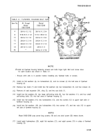
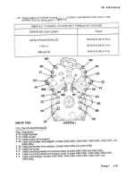
TABLE 3-1. FLYWHEEL HOUSING BOLT SIZE
Item No.
All Except
Model
Model
5063-5398
5063-5398
4
3/8-16 X 2 1/2
3/8-16 X 2 3/4
8
5/16-18 X 2 1/2
5/16-18X21/2
10
3/8-16 X 2 1/2
3/8-16 X 2 3/4
12
3/8-24 X 3 1/4
3/8-24 X 3 1/4
17
3/8-24 X 3 1/2
3/8-24 X 3 1/2
19
3/8-16 X 3 3/4
3/8-16 X 4
35
—
3/8-16 X 3 7/8
NOT E
Ž
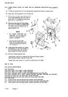
Install all flywheel housing fastening screws and bolts finger tight. Bolt and screw sizes
for each location are shown in Table 3-1.
•
Ensure shim (24) is in position before installing any flywheel bolts or screws.
(11)
(12)
(13)
(14)
(15)
(16)
(17)
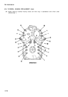
Install six flat washers (6), six Iockwashers (5), and six screws (4) into bell area of flywheel
housing (2).
Remove two studs (7) and install two flat washers (6), two Iockwashers (5), and two screws (4).
Remove oil seal expander (34), sling (3), and two eye bolts (1).
Install two flat washers (9), two large self-locking bolts (8), four flat washers (11), and four small
self-locking bolts (10) into bell area of flywheel housing (2).
Install two flat washers (14), two Iockwashers (13), and two screws (12) to upper right side of
flywheel housing (2).
Install two flat washers (18), two Iockwashers (16), two screws (17), and two nuts (15) to upper
left side of flywheel housing (2).
NOT E
Model 5063-5398 uses seven long screws (19) and one short screw (35) where shown.
Install eight Iockwashers (20), eight flat washers (21), and eight screws (19) in sides of flywheel
housing (2).
3-145
Back to Top


