TM-9-2815-205-34 - Page 266 of 596
TM 9-2815-205-34
(9) Remove two nuts (2), two flat washers (3), and lifting fixture (1) from cylinder head.
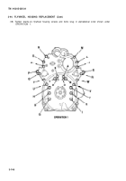
(10) Remove two guide studs (6) and install remaining bolts (5). Torque all bolts to 15-20 Ib-ft (20-27
NŽm).
NOT E
Repeat tightening sequence at least once because first bolts tightened tend to lose
significant clamping load during tightening of remaining bolts. Apply a steady pressure
for two or three seconds at prescribed torque to allow bolts to turn while gaskets yield to
their designed thickness.
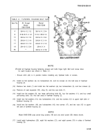
(11) Torque cylinder head bolts (5) to 170-180 Ib-ft (231-244 NŽm) in 50 Ib-ft (68 N•m) increments
Tighten bolts in alphabetical sequence shown.
(12) Repeat steps (3) thru (11) for left bank.
END OF TASK
FOLLOW-ON MAINTENANCE
Para
3-42
3-32
3-31
3-20
3-21
3-22
3-16
3-17
3-18
3-19
3-14
3-15
3-7
Description
Install injector control tubes.
Install fuel rod hoses
Install throttle control rods.
Install engine rocker arm covers (models 5063-5299 and 5063-5398).
Install engine rocker arm covers (models 5063-5392, 5063-5393, 5063-539F, and 5063 -539 L).
Install engine rocker arm covers (model 5063-5395).
Install fuel lines (model 5063-5299).
Install fuel lines (model 5063-5392).
Install fuel lines (models 5063-5393 and 5063-539L).
Install fuel lines (models 5063-5395, 5063-5398, and 5063-539F).
Install water outlet elbow and thermostat housing (all except models 5063-5393 and 5063-539L).
Install water outlet elbow and thermostat housing (models 5063-5393 and 5063-539L).
1
Install exhaust manifolds.
Change 1
3 -137/(3 -138 blank)
Back to Top

