TM-9-2815-205-34 - Page 263 of 596
TM 9-2815-205-34
3-43. CYLINDER HEAD ASSEMBLY REMOVAL/INSTALLATION (Cont)
(8)
(9)
(10)
(11)
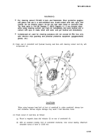
Remove lifting fixture (1), two nuts (2), and two flat washers (3) from cylinder head assembly.
Repeat steps (1) thru (8) for opposite bank.
On all except model 5063-5299: for left bank, remove bolt (17), Iockwasher (18), and clip (19)
from rear of cylinder head assembly. If necessary, remove clip from fuel spill tube (20). Discard
Iockwasher.
For left bank, remove fuel spill tube (20) from elbow (21) at rear of cylinder head assembly.
(1)
(2)
(3)
3-134
Connect fuel spill tube (20) to elbow (21). Tighten tube connection.
On all except model 5063-5299 for left bank: if removed, install clip (19) on fuel spill tube (20)
and install bolt (17), Iockwasher (18), and clip on rear of cylinder head assembly. Torque bolt to
23-26 Ib-ft (31-35 N
.
m).
Install lifting fixture (1), two flat washers (3), and two nuts (2) on exhaust manifold studs (4) on
outboard side of cylinder head.
b. Installation
Back to Top


