TM-9-2815-205-34 - Page 342 of 596
TM 9-2815-205-34
3-51. PISTON AND CONNECTING ROD MAINTENANCE - CROSS-HEAD (MODELS 5063-5392,
5063-5393, 5063-539F, AND 5063-539L) (Cont)
CAUTION
(5)
(6)
(7)
(8)
(9)
Distance from vertical center
line of connecting rod bolts to
edges of rod are not equal.
When installing piston and con-
netting rod assembly, ensure
narrow side of two adjoining
connecting rods are together to
avoid cocking of rod.
Do not damage or dislocate
bearing shell when guiding end
of connecting rod assembly
through block bore.
Do not damage preformed
packings when sliding piston,
connecting rod, and liner as-
sembly into block bore.
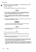
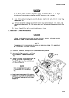
Position piston, rod, and liner assembly (33) in line with cylinder block bore. Align identification
number and letter on rod face with outer edge of cylinder block and matchmarks on liner. Guide
end of connecting rod (17) through block bore. Then slide piston, connecting rod, and liner
assembly straight into block bore until liner flange rests against block counterbore (34).
Push piston into liner until upper bearing shell (32) is firmly seated on crankshaft journal (4).
NOT E
Tang on bearing shell must fit in indentation in connecting rod cap.
Place lower bearing shell (7) (with continuous oil groove) in connecting rod cap (6).
NOT E
Connecting rod bolt must not turn in connecting rod when torquing nut.
To check bearing to crankshaft journal clearance, place a plastic gage strip (35) between
crankshaft journal (4) and connecting rod cap (6). Tighten connecting rod nuts (5) to 40-45 Ib-ft
(54-61 N·m.). Remove connecting rod nuts and cap, and measure width of plastic gage with
measuring strip (36). Maximum clearance with used parts is 0.006 inch.
Lubricate lower bearing shell (7) with clean engine oil and install bearing cap (6) and bearing
shell on connecting rod (17) with identification numbers on cap and rod adjacent to each other
Torque connecting rod bolt nuts (5) to 40-45 Ib-ft (54-61 N·m).
3-212
Change 1
Back to Top


