TM-9-2815-205-34 - Page 99 of 596
TM 9-2815-205-34
2-28. AIR BOX DRAINS REMOVAL/INSTALLATION (MODELS 5063-5395 AND 5063-539F)
This task covers: a. Removal
b. Installation
INITIAL SETUP
MODELS
MATERIALS/PARTS
5063-5395 5063-539F
1
Lockwashers (App F, Item 98)
TOOLS AND SPECIAL TOOLS
EQUIPMENT CONDITION
Tool kit, general mechanics (App B, Item 107)
Para Description
Wrench, torque (App B, Item 116)
2-25 Electric starter removed,
a. Removal
(1)
(2)
(3)
(4)
(5)
(6)
(7)
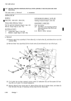
Disconnect right air box drain tube assembly (1) from elbow (2).
Remove bolt (3) and lockwasher (4) securing clip (5) on air box drain tube assembly (1) to right
side of cylinder block. Discard lockwasher. If necessary, remove clip from tube assembly.
Remove air box drain tube assembly (1) from elbow (6) in right side of cylinder block.
Remove elbow (6) from right side of cylinder block.
Remove air box drain tube assembly (7) from elbow (8) in left side rear of cylinder block.
Disconnect air box drain tube assembly (7) from elbow (9).
Remove elbow (8) and pipe coupling (10) from left side of cylinder block.
b. Installation
(1)
(2)
(3)
(4)
(5)
(6)
(7)
Install pipe coupling (10) in left side of cylinder block. Install elbow (8) in coupling with port
facing front of engine.
Connect air box drain tube assembly (7) to elbow (9).
Install air box drain tube assembly (7) in elbow (8) on left side of cylinder block
securely.
Install elbow (6) in right side of cylinder block with port facing front of engine.
Connect air box drain tube assembly (1) to elbow (2).
Tighten
Install air box drain tube assembly (1) in elbow (6) on right side of cylinder block. Tighten
securely.
If removed, install clip (5) on air box drain tube assembly (1). Install lockwasher (4) and bolt (3),
through clip on air box drain tube assembly, into right side of cylinder block. Torque bolt to
13-17 lb-ft (18-23 N•m).
2-72
Back to Top


