TM-9-2815-210-34-2-2 - Page 339 of 968
TM 9-2815-210-34-2-2
FRAME 4
NOTE
Readings must be within limits given in table 4-59.
The letter L shows a loose fit.
If readings are not
within given limits, throw away part and get a new
one.
1.
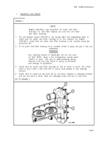
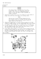
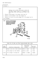
Measure inside diameter of two bypass valve bores (1).
2.
Measure out side diameter of two valve plungers (2).
3.
Measure fit of each of two valve plungers (2) in its plunger bore (1).
GO TO FRAME 5
Index
Number
1
2
1 and 2
Table 4-59. Oil Cooler and Filter Housing Assembly Wear Limits
Item/Point of Measurement
Bypass valve bores inside diameter
Valve plungers out side diameter
Fit of plunger in housing bore
Size and Fit
of New Parts
(inches)
0.8030 to 0.8040
0.8000 to 0.8010
0.0020L to 0.0040L
Wear Limit
(inches)
0.8050
0.7990
0.0060L
4-320
Back to Top

