TM-9-2815-210-34-2-2 - Page 721 of 968
TM 9-2815-210-34-2-2
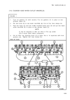
FRAME 5
1.
2.
3.
4.
5.
NOTE
Cylinders are called number one through six counting
from front to rear of engine. Each cylinder has one in-
take valve and one exhaust valve. Intake valve for
each cylinder is toward front of cylinder and exhaust
valve is toward rear of cylinder.
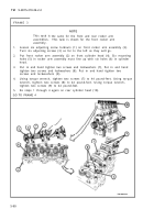
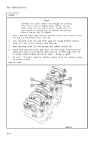
Slide 0.025-inch feeler gage between cylinder number one exhaust rocker
arm pad (1) and exhaust valve stem (2).
Turn adjusting screw (3) until feeler gage fits snugly between cylinder
number one exhaust rocker arm pad (1) and exhaust valve stem (2).
Keep adjusting screw (3) from turning and tighten locknut (4).
Check that 0.025-inch feeler gage blade still fits snugly between exhaust
rocker arm pad (1) and exhaust valve stem (2). If feeler gage does not
fit snugly, loosen locknut (4) and do steps 1 through 4 again.
Do steps 1 through 4 again for cylinder number two and cylinder number
four exhaust valves.
GO TO FRAME 6
5-92
Back to Top


