TM-9-2815-210-34-2-2 - Page 716 of 968
TM 9-2815-210-34-2-2
FRAME 2
Soldiers
A and B
NOTE
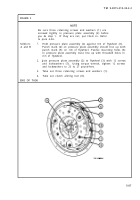
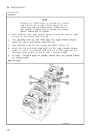
Be sure three retaining screws and washers (1) are
screwed tightly in pressure plate assembly (2) before
you do step 1.
If they are not, put them in. Refer
to para 4-56.
1.
2.
3.
4.
END OF TASK
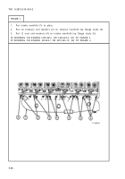
Hold pressure plate assembly (2) against rim of flywheel (3).
Punch mark (4) on pressure plate assembly should line up with
punch mark (5) on rim of flywheel. Twelve mounting holes (6)
in pressure plate assembly must line up with threaded holes in
rim of flywheel.
Join pressure plate assembly (2) to flywheel (3) with 12 screws
and lockwashers (7).
Using torque wrench, tighten 12 screws
and lockwashers to 23 to 27 pound-feet.
Take out three retaining screws and washers (1).
Take out clutch alining tool (8).
5-87
Back to Top


