TM-5-2350-377-14-P - Page 112 of 335
TM 5-2350-377-14&P
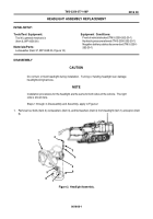
DISASSEMBLY
NOTE
Steps 1 through 4 apply to Figure 1.
1. Remove control box power harness connector (item 1) from track & blade control box (item 2).
2. Remove manifold harness connector (item 3) from track & blade control box (item 2).
3. Remove two screws (item 6) and two washers (item 5) from instrument panel (item 4).
4. Slide track & blade control box (item 2) upward from behind instrument panel (item 4).
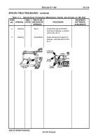
Figure 1.
Track & Blade Control Box.
TRACK & BLADE CONTROL BOX REPLACEMENT
0015 00
0015 00-1
6
2
5
1
3
4
6
5
Equipment Conditions
Negative battery cables disconnected (TM 5-2350-
262-20-1)
INITIAL SETUP
Tools/Test Equipment
Tool kit, general mechanic's
(Item 6, WP 0056 00)
Back to Top

