TM-9-1200-215-34-P - Page 138 of 266
TM 9–1200–215–34&P
4–24
4–21.
COVER, ELECTRICAL CONNECTOR
DESCRIPTION
This task covers:
a.
Removal
b.
Installation
INITIAL SETUP
Tools:
Tool Kit, JTK–17LAL (item 34, Appendix E)
Tool Kit, General Mechanic’s (item 42, Appendix E)
Socket, Socketwrench (1–9/16 in. hex, 3/4 in. dr)
(item 46, Appendix E)
Socket, Socketwrench (2.0 in. hex, 3/4 in. dr)
(item 19, Appendix E)
Adapter, Socketwrench (1/2 in. x 3/4 in.)
(item 1, Appendix E)
Pliers, Wire Twister (item 47, Appendix E)
Materials/Parts:
Wire, Safety (item 30, Appendix D)
Equipment Condition:
Unenergized PDIU on work bench
Personnel Required:
One MOS 35Y
a.
REMOVAL
1.
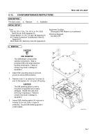
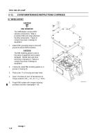
Unscrew cover (1) from connector (2).
NOTE
Note the path of the safety wire.
2.
Cut safety wire (3) from nut (4) and the
connecting loops on adjacent nut(s).
Remove
wire.
3.
Remove nut (4), cover (1), and collar (5) from
connector (2).
b.
INSTALLATION
1.
Install collar (5) with nut (4) on connector (2).
2.
Install cover (1) on connector (2).
3.
Install safety wire (3) between nut (4 and
adjacent nut(s).
Wire turns must begin
immediately at one nut and continue to the
adjacent nut.
A minimum of five turns per inch
should be made to complete the loop at the
end of the wire.
Change 1
1
2
2
1
3
5
4
5
4
Back to Top


