TM-9-1200-215-34-P - Page 144 of 266
TM 9–1200–215–34&P
5–6
Section
V
.
MAINTENANCE PROCEDURES
Page
Page
General
5–6
. . . . . . . . . . . . . . . . . . . . . . . . . . . . . . . . . .
Cover Maintenance Instructions
5–7
. . . . . . . . . . . . .
Indicator Maintenance Instructions
5–9
. . . . . . . . . . .
CCA Maintenance Instructions
5–11
. . . . . . . . . . . . .
Heatsink Assembly Maintenance
Instructions
5–13
. . . . . . . . . . . . . . . . . . . . . . . . . . . . .
Cable Assembly Maintenance
Instructions
5–15
. . . . . . . . . . . . . . . . . . . . . . . . . . . . .
5–12.
GENERAL
a.
This section contains the step–by–step maintenance procedures for DS level maintenance of the VMS
Modem.
These procedures are provided to access components for general maintenance.
These maintenance
tasks are authorized by the Source, Maintenance, and Recoverability (SMR) codes indicated in the RPSTL in
Appendix C.
There are no GS level maintenance tasks for the VMS Modem.
b.
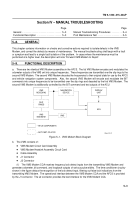
The diagram below shows the location of each of the main replaceable assemblies in the VMS Modem:
LEGEND:
(1)
COVER
(2)
EMI SHIELDING GASKET
(3)
CCA
(4)
HEATSINK ASSEMBLY
(5)
CABLE ASSEMBLY
(6)
ELECTRONIC HOUSING
(7)
POWER LED
Figure 5–3.
VMS Modem Exploded View
1
2
3
4
5
6
7
Back to Top

