TM-9-1200-215-34-P - Page 153 of 266
TM 9–1200–215–34&P
5–15
5–17.
CABLE ASSEMBLY MAINTENANCE INSTRUCTIONS
DESCRIPTION
This task covers:
a.
Removal
b.
Installation
INITIAL SETUP
Tools:
Tool Kit, JTK–17LAL, TK–101/G, or TK–105/G
(items 34, 35, & 36, Appendix E)
Torque Wrench, 0–150 in.–lb (item 41, Appendix E)
Work Station Kit, Electronic (item 38, Appendix E)
1–5/8” x 3/4” Drive Socket (item 17, Appendix E)
Equipment Condition:
Heatsink assembly removed; if not, remove heatsink
assembly in accordance with procedure outlined in
paragraph 5–16.
Indicator removed; if not, remove indicator in accor-
dance with procedure in paragraph 5–14.
Personnel Required:
One MOS 35Y
a.
REMOVAL
CAUTION
ESD SENSITIVE
The VMS Modem contains ESD
sensitive components.
Wear a
protective ESD wrist strap whenever
handling components.
Failure to
comply may result in damage to
equipment.
1.
Attach ESD grounding strap to wrist and
ground to ensure ESD protection.
2.
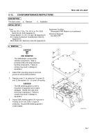
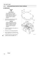
Remove jam nuts (1) from cable assembly
connectors J1 (2) and J2 (3).
3.
Remove cable assembly connectors J1 (2) and
J2 (3) from VMS modem housing (4).
CAUTION
The EMI shielding gasket is vital to
this piece if equipment and is easily
damaged. Handle with care when
removing or replacing it. Gasket will
break if stretched. Failure to comply
may result in damage to equipment.
4.
Remove EMI shielding gaskets (5 and 6) from
J1 (2) and J2 (3) connectors.
5.
Inspect EMI shielding gaskets (5 and 6) for
cuts, nicks, and signs of stretching. Discard
EMI shielding gasket if unserviceable.
6.
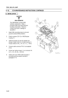
Pull cable assembly (7) from VMS Modem
housing (4).
2
3
4
5
6
7
TO LED’S
1
Back to Top


