TM-9-1200-215-34-P - Page 154 of 266
TM 9–1200–215–34&P
5–16
5–17.
CABLE ASSEMBLY MAINTENANCE INSTRUCTIONS CONTINUED
b.
INSTALLATION
CAUTION
ESD SENSITIVE
The VMS Modem contains ESD
sensitive components.
Wear a
protective ESD wrist strap whenever
handling components.
Failure to
comply may result in damage to
equipment.
1.
Attach ESD grounding strap to wrist and
ground to ensure ESD protection.
CAUTION
The EMI shielding gasket is vital to
this piece if equipment and is easily
damaged. Handle with care when
removing or replacing it. Gasket will
break if stretched. Failure to comply
may result in damage to equipment.
NOTE
If a new cable is installed it may be
necessary to remove jam nuts prior
to next step.
2.
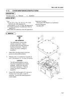
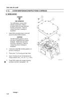
Position EMI shielding gaskets (5 and 6) onto
J1 (2) and J2 (3) connectors.
3.
Place J1 connector (2) and J2 connector (3)
into position in VMS Modem housing (4). Place
jam nuts (1) on J1 and J2 connectors and
hand tighten.
4.
Torque jam nut (1) on connector J1 (2) to 70+5
in.–lb (7.9+ .6 N
S
m) and jam nut (1) on
connector J2 (3) to 60+5 in.–lb ( 6.8+ .6 N
S
m).
5.
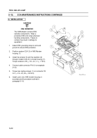
Install heatsink assembly IAW procedure
outlined in paragraph 5–16.
6.
Install indicator IAW procedure outlined in
5–14.
2
3
4
5
6
TO LED’S
1
Back to Top


