TM-9-1200-215-34-P - Page 157 of 266
TM 9–1200–215–34&P
6–3
Section
IV – MANUAL TROUBLESHOOTING.
Page
Page
General
6–3
. . . . . . . . . . . . . . . . . . . . . . . . . . . . . . . . . .
Functional Description
6–3
. . . . . . . . . . . . . . . . . . . . .
Troubleshooting Procedures
6–8
. . . . . . . . . . . . . . . .
Post–Maintenance Test
6–8
. . . . . . . . . . . . . . . . . . . .
6–8.
GENERAL
This chapter contains information on checks and corrective actions required to isolate defects in the Power
Conditioning Unit (PCU), and correct the defects by means of maintenance.
The troubleshooting shall begin with
a fault or symptom and lead to a single fault isolation of the problem.
In cases where the maintenance must be
performed at a higher level, the description will note “Forward PCU to Depot”.
6–9.
FUNCTIONAL DESCRIPTION
a.
The Power Conditioning Unit (PCU) provides conditioned (filtered and supported) power to the AFCS plus
unconditioned (unfiltered and unsupported) power to components outside of the AFCS. The PCU utilizes 14 volt
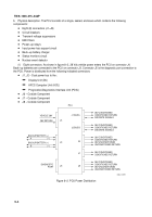
storage batteries (back–up batteries) to supplement host vehicle power to the AFCS. A block diagram of the PCU
is shown in Figure 6–1 below.
J4
50A
J7
RADIO
RACK
15A
20A
10A
20A
10A
J6
J8
IR/NS
LEU
IR/NS OUTPUT
LEU OUTPUT
RADIO OUTPUT
BACKUP BATTERY
J5
DIAG–
NOSTIC
PORT
POWER
BUS A
POWER
BUS B
20A
20A
J1
J2
VOLTAGE
DOUBLER
RELAY
J3
BACKUP
BATTERIES
BATTERY
CHARGER
MONITORS
AND
CONTROL
AND
NUCLEAR
EVENT
DETECTOR
40A
40A
VEHICLE
POWER
RELAY
EMI
FILTER
EMI
FILTER
28V CONDITIONED RETURN
28V
CONDITIONED
POWER
28V UNCONDITIONED POWER
28V UNCONDITIONED RETURN
Figure 6–1. PCU Block Diagram
Back to Top


