TM-9-1200-215-34-P - Page 148 of 266
TM 9–1200–215–34&P
5–10
5–14.
INDICATOR MAINTENANCE INSTRUCTIONS CONTINUED
b.
INSTALLATION
CAUTION
ESD SENSITIVE
The VMS Modem contains ESD
sensitive components.
Wear a
protective ESD wrist strap whenever
handling components.
Failure to
comply may result in damage to
equipment.
1.
Attach ESD grounding strap to wrist and
ground to ensure ESD protection.
2.
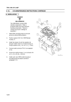
Clean, straighten, and retin ends of wires (6
and 7).
Slide jam nut (4) and lockwasher (5)
over wires.
Insert wires through hole.
3.
Place 1.5 + 0.5 inch (30 + 10 mm) of new
insulation sleeving (8) on each wire (6 and 7)
and push back away from bare portion of wire
to allow for soldering.
4.
Clean solder posts (9 and 10) using type
cleaner and soldering aid tool.
Coat solder
posts with solder flux prior to soldering.
5.
Solder wires (6 and 7) to appropriate indicator
base post (9 and 10).
Remove marker bands.
6.
Push insulation sleeving (8) up wire to base of
indicator (2).
Shrink insulation sleeving around
wires and indicator base solder posts.
7.
Insert indicator base (2) into modem housing.
8.
Place lockwasher (5) and jam nut (4) on
indicator base (2) and hand tighten.
9.
Torque indicator base jam nut (4) to 20 + 1
in.–lb (2.3 + 1 N
S
m).
10. Insert LED (3) into indicator cap (1) and push
gently until fully seated.
11.
Screw indicator cap (1) into indicator base (2)
until fully seated.
12. Install cover in accordance with procedure
outlined in paragraph 5–13.
1
3
2
6
7
8
8
4
5
10
9
Back to Top


