TM-9-1200-215-34-P - Page 133 of 266
TM 9–1200–215–34&P
4–19
4–18
ELECTRICAL INDICATOR PANEL CONTINUED
c.
INSTALLATION CONTINUED
6.
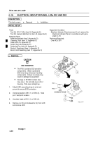
Attach connectors P3 (10) and P4 (11) to
connectors on filter assembly (6).
Tighten four
connector retaining screws (9).
7.
Attach connector P5 (7) to connector J8 (8)
and latch in place.
8.
Install eight flat washers (3), eight lockwashers
(2), and eight screws (1) to secure two tiebars
(4 and 5) to filter assembly (6).
9.
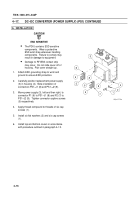
Install DC–DC converter, PS1 in accordance
with paragraph 4–17.
3
5
1
2
4
10
9
7
8
61
1
Back to Top


