TM-9-1200-215-34-P - Page 91 of 266
TM 9–1200–215–34&P
2–56
2–25.
ACU HANDLE MAINTENANCE INSTRUCTIONS CONTINUED
b.
INSTALLATION CONTINUED
1.
Attach ESD grounding strap to wrist and
ground to ensure ESD protection.
2.
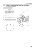
If removed, install gaskets (15) on handle (12).
3.
Install handle (12) on ACU with two nuts (13)
and two star washers (14).
Torque screws to
20 ft–lb (27.1 N
S
m).
4.
Carefully position CPU CCA (10) onto
backplane (11).
5.
Secure CPU CCA (10) to backplane (11) by
pushing down firmly on CCA.
NOTE
Ensure that hole in heatsink and
transistor are aligned with spacer
assembly before installing
hardware.
6.
Install CPU CCA heatsink (6) between
transistor and CPU CCA and insert screw (5)
into spacer assembly in ACU. Torque
screw to
5 in.–lb (0.6 N
S
m).
7.
Tighten screw (9) in Loktainer of CPU CCA.
Torque screw to 25 in.–oz.
8.
Insert screw (7) and flat washers (8) into
holddown of CPU CCA.
Torque screws to 5
in.–lb (0.6 N
S
m).
9.
Install two insulating blocks (1) by inserting
three screws (2), three new lockwashers (3),
and three flat washers (4).
10. Install stabilizer brackets in accordance with
procedure outlined in paragraph 2–14.
11.
Install hard disk drive (16) into ACU.
12. Insert four new screws with seals (17) into side
of ACU, securing hard disk drive (16).
Torque
screws to 10 in.–lb (1.1 N
S
m).
13. Install top panel in accordance with procedure
outlined in paragraph 2–13.
Change 1
1
1
2
3
4
2
4
5
6
7
8
9
10
11
12
12
13
13
14
14
15
16
17
Back to Top


