TM-9-1200-215-34-P - Page 81 of 266
TM 9–1200–215–34&P
2–46
2–23.
CONNECTOR PANEL ASSEMBLY WITH MAIN CABLE MAINTENANCE
INSTRUCTIONS CONTINUED
a.
REMOVAL CONTINUED
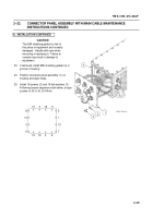
12. Gently loosen CPU CCA (20) from backplane
(21).
Do not remove from ACU housing.
13. Disconnect three ribbon cables (22, 23, and
24), J5, J7, and J9, respectively, from back of
CPU CCA (20).
14. Disconnect mouse cable (25) from back edge
of CPU CCA (20).
15. Disconnect cable connector (26) from J1
connector (27) at the top of the Power Supply
assembly (28).
16. Remove clamp (29) securing cable (30) to
ACU housing, by removing screw (31),
lockwasher (32) and flat washers (33).
Discard lockwasher.
17. Cut leads (34) from rear of two LEDs (35).
18. Remove lockwire (36).
Discard lockwire.
19. Remove two connectors J5 (37) and J6 (38) by
removing two jam nuts (39) and two preformed
packings (40) from the outside of the ACU.
Discard preformed packings.
20. Pull connectors (37) and (38) out of housing.
21. Disconnect cable connectors (41, 42, and 43)
from backplane (21) at J15, J16, and J17,
respectively, by loosening two captive screws
(44) on each connector.
22. Remove screw (45) from cable tie (46)
securing main cable assembly (47) to housing.
23. Remove connector panel assembly (1) with
main cable assembly (47) from ACU.
1
20
23
22
24
25
31
32
33
29
30
26
44
43
42
44
41
27
28
35
47
46
45
38
40
39
36
34
39
40
37
21
Back to Top


