TM-9-1200-215-34-P - Page 80 of 266
TM 9–1200–215–34&P
2–45
2–23.
CONNECTOR PANEL ASSEMBLY WITH MAIN CABLE MAINTENANCE
INSTRUCTIONS CONTINUED
a.
REMOVAL CONTINUED
NOTE
Tag all cables before removing to
aid in the installation.
1.
Attach ESD grounding strap to wrist and
ground to ensure ESD protection.
2.
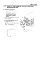
Remove ACU connector panel assembly (1) by
removing 16 screws (2) and 16 flat washers
(3).
Lift connector panel assembly off housing.
CAUTION
The EMI shielding gasket is vital to
this piece of equipment and is easily
damaged.
Handle with care when
removing or replacing it.
Failure to
comply may result in damage to
equipment.
3.
Inspect EMI shielding gasket (4) for cuts,
nicks, or signs of stretching.
Discard EMI
shielding gasket if unserviceable.
4.
Remove top panel in accordance with
procedure outlined in paragraph 2–13.
5.
Remove stabilizer brackets in accordance with
procedure outlined in paragraph 2–14.
6.
Remove two insulating blocks (5) by removing
three screws (6), three lockwashers (7) and
three flat washers (8).
Discard lockwashers.
7.
Loosen two captive screws (9) securing card
edge connector (10) to TCIM CCA (11).
8.
Disconnect channel connector (12) from J2
connector (13) located on card edge of 1553
CCA (14).
9.
Remove screw (15) and CPU CCA heatsink
(16) from spacer assembly in ACU.
10. Remove screw (17) and flat washer (18) from
holddown of CPU CCA.
11.
Loosen screw (19) (approximately six turns) in
Loktainer of CPU CCA.
8
7
6
8
7
6
11
13
2
3
1
12
10
9
14
5
5
15
16
17
18
4
19
Back to Top


