TM-9-1200-215-34-P - Page 83 of 266
TM 9–1200–215–34&P
2–48
2–23.
CONNECTOR PANEL ASSEMBLY WITH MAIN CABLE MAINTENANCE
INSTRUCTIONS CONTINUED
b.
INSTALLATION CONTINUED
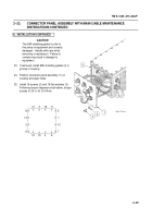
12. Connect three ribbon cables (22, 23, and 24) and
mouse cable J13 (25) to back of CPU CCA in the
following sequence: J9, J5, J13, and J7.
13. Position CPU CCA (20) onto backplane (21) in
ACU housing and secure by pushing down
firmly on CCA.
NOTE
Ensure that hole in heatsink and
transistor are aligned with spacer
assembly before installing
hardware.
14. Install CPU CCA heatsink (16) between
transistor and CPU CCA and insert screw (15)
into spacer assembly in ACU. Torque screw to
5 in.–lb (0.6 N
S
m).
15. Tighten screw (19) in Loktainer of CPU CCA
and torque to 25 in.–oz.
16. Insert screw (17) and flat washer (18) into
holddown of CPU CCA. Torque screw to 5
in.–lb (0.6 N
S
m).
17. Connect channel connector (12) to J2
connector (13) located on card edge of 1553
CCA (14).
18. Connect connector (10) to card edge of TCIM
CCA (11) and secure by tightening two captive
screws (9).
19. Install two insulating blocks (5) by inserting
three screws (6), three new lockwashers (7)
and three flat washers (8).
20. Secure main cable assembly (47) to housing
by installing cable tie (46) with screw (45).
21. Install stabilizer brackets in accordance with
procedure outlined in paragraph 2–14.
22. Install top panel in accordance with procedure
outlined in paragraph 2–13.
12
10
9
8
7
6
8
7
6
11
13
14
5
5
15
16
17
18
19
23
22
24
25
45
46
47
21
20
Back to Top


