TM-9-1200-215-34-P - Page 90 of 266
TM 9–1200–215–34&P
2–55
2–25.
ACU HANDLE MAINTENANCE INSTRUCTIONS CONTINUED
a.
REMOVAL CONTINUED
3.
Remove stabilizer brackets in accordance with
procedure outlined in paragraph 2–14.
4.
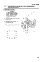
Remove two insulating blocks (1) by removing
three screws (2), three lockwashers (3), and
three flat washers (4).
Discard lockwashers.
5.
Remove screw (5) and CPU CCA heatsink (6)
from spacer assembly in ACU.
6.
Remove screw (7) and flat washer (8) from
holddown of CPU CCA.
7.
Loosen screw (9) (approximately six turns) in
Loktainer of CCA.
8.
Gently loosen CPU CCA (10) from backplane
(11).
Do not remove from ACU housing.
9.
Remove handle (12) by removing two nuts (13)
and two star washers (14).
10. Inspect gaskets (15) on handle for cuts, nicks,
or signs of stretching.
Discard gasket if
unserviceable.
NOTE
Screw and seal are a unit. They
cannot be requisitioned separately.
11.
Remove hard disk drive (16) from ACU by
removing four screws with seals (17) on side
of ACU. Discard screws with seals.
b.
INSTALLATION
ESD SENSITIVE
The ACU contains ESD sensitive
components. Wear a protective
ESD wrist strap whenever handling
components. Failure to comply may
result in damage to equipment.
NOTE
When installing handle to left side of
ACU, perform steps 1 through 10
and 13.
When installing handle to
right side of ACU, perform steps 1,
2, 3, 11, 12, and 13.
Change 1
1
1
2
3
4
2
4
5
6
7
8
9
10
11
12
12
13
13
14
14
15
16
17
Back to Top


