TM-9-2330-342-23-P - Page 785 of 1348
INSTALLATION - Continued
NOTE
Pulley is properly installed when screw and locknut are tightened and bracket rotate freely.
6.
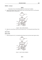
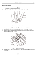
Install pulley (Figure 11, Item 3), spacer (Figure 11, Item 4), two washers (Figure 11, Item 2), screw (Figure
11, Item 1), and locknut (Figure 11, Item 5) on pulley support bracket (Figure 11, Item 7).
7.
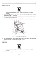
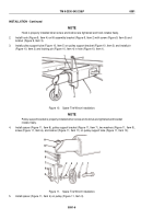
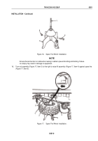
Remove locking pin (Figure 12, Item 3) and pin (Figure 12, Item 1) from pulley support tube (Figure 12, Item
4) and return pulley support tube to retracted position.
1
2
3
4
Figure 12.
Spare Tire Winch Installation.
8.
Install pin (Figure 12, Item 1) through pulley support tube bracket (Figure 12, Item 2) and pulley support tube
(Figure 12, Item 4) and install locking pin (Figure 12, Item 3).
9.
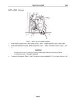
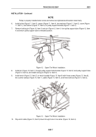
Install winch (Figure 13, Item 7) on winch bracket (Figure 13, Item 8) with three screws (Figure 13, Item 6),
two cushion clamps (Figure 13, Item 1), cable (Figure 13, Item 3), and three locknuts (Figure 13, Item 2).
6
7
8
1
2
3
4
5
Figure 13.
Spare Tire Winch Installation.
10.
Pay winch cable (Figure 13, Item 5) down through hole in tire carrier (Figure 13, Item 4).
TM 9-2330-342-23&P
0091
0091-7
Back to Top

